One of the primary factors in calculating aircraft cg is the distribution of weight across the aircraft. This involves determining the location of the various components, including the fuselage, wings, engines, and other systems. Each component contributes to the overall weight, and their respective positions play a significant role in establishing the center of gravity.
An important concept in calculating aircraft cg is the moment arm. The moment arm is the perpendicular distance from a reference point to the line of action of a force. In the context of aviation, it refers to the distance from the reference point to the center of gravity. The moment arms of all the components must be considered to accurately determine the center of gravity.
Engineers and aviators use specific calculations to find the center of gravity during the design and operation of an aircraft. These calculations take into account the weight of each component, its moment arm, and the aircraft’s total weight. The goal is to ensure that the center of gravity falls within a specified range, preventing the aircraft from being too nose-heavy or tail-heavy, which could lead to instability.
Additionally, calculating aircraft cg involves accounting for variable factors, such as fuel consumption. As fuel is burned during flight, the weight distribution changes, impacting the center of gravity. Pilots and ground crew must constantly monitor these changes and adjust as needed to maintain optimal balance.
In aviation, safety is paramount. Incorrectly calculating aircraft cg can result in serious consequences, including loss of control and potential accidents. Therefore, precise calculations and adherence to specified limits are crucial in both the design phase and the operational phase of an aircraft.
To facilitate the understanding of how to calculate aircraft cg, the use of tables and visual aids is common. These tools provide a clear representation of the weight distribution and moment arms, aiding engineers, pilots, and maintenance crews in making informed decisions to ensure the aircraft’s optimal performance and safety.
Determining forward and aft aircraft cg limits for balance and stability
When determining forward and aft aircraft cg limits for balance and stability, meticulous calculations and considerations come into play. The center of gravity (CG) is a crucial parameter that directly impacts the aircraft’s flight characteristics. Striking the right balance between forward and aft limits is essential for safe and optimal performance.
Firstly, let’s delve into the significance of the forward CG limit. This limit is defined as the most forward position where the aircraft’s CG can be located. Operating within this limit ensures stability during different flight phases. A forward CG enhances maneuverability and responsiveness, making the aircraft more nimble in the skies. Pilots, however, need to be cautious not to surpass this limit as it could lead to increased nose-heavy tendencies, affecting pitch control and potentially causing a stall.
Conversely, the aft CG limit is the furthest position to the rear where the CG can be positioned. An aircraft operating within the aft CG limit is generally more stable but may sacrifice some agility. This position can enhance fuel efficiency and, in some cases, provide better cruise performance. However, exceeding the aft CG limit can result in a tail-heavy configuration, leading to difficulties in controlling pitch and potentially compromising stall recovery.
It’s important to note that aircraft manufacturers meticulously define these limits based on extensive testing and analysis. The limits are often represented as a range, allowing pilots to adjust the CG within specified boundaries depending on factors like fuel load, cargo distribution, and passenger placement.
One method to visualize these limits is through the use of a CG envelope chart. This graphical representation displays the safe operating range for CG and helps pilots make informed decisions regarding weight distribution. The chart typically includes zones for normal, utility, and aerobatic operations, each with its own set of forward and aft CG limits.
Factors influencing CG limits include the aircraft’s design, configuration, and intended use. For instance, transport aircraft may have more conservative CG limits compared to aerobatic or military aircraft designed for specific performance characteristics. Understanding and adhering to these limits are imperative for flight safety and optimal aircraft performance.
Locating the aircraft cg on the datum line for proper balance

When considering aircraft balance, the datum line plays a pivotal role in determining the position of the aircraft’s center of gravity (CG). The datum line serves as the reference point from which all measurements are taken, creating a standardized framework for assessing the longitudinal and lateral aspects of the aircraft’s balance.
The datum itself is an imaginary vertical line that runs through the aircraft, typically passing through the nose or a specified point on the fuselage. This establishes a consistent baseline for calculations related to weight distribution. Properly identifying and utilizing the datum line is crucial for ensuring the CG is within acceptable limits.
For precise balance, the longitudinal position of the CG is meticulously determined concerning the datum line. This refers to the forward and backward movement of the CG along the aircraft’s length. Maintaining the longitudinal balance is essential for stability during various flight conditions, preventing issues such as nose-heaviness or tail-heaviness.
Simultaneously, the lateral position of the CG is assessed concerning the datum line’s lateral axis. This involves the side-to-side distribution of weight. Proper lateral balance ensures that the aircraft remains level and avoids unwanted rolling tendencies. Pilots and engineers carefully calculate the lateral position of the CG to optimize handling and maneuverability.
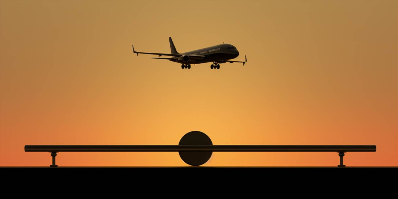
Imagine the datum line as the fulcrum of a seesaw, with the aircraft’s weight distributed on either side. Striking the right balance along both the longitudinal and lateral axes is akin to achieving harmony on this aerial seesaw, where the position of the CG ensures equilibrium and controlled flight.
To facilitate understanding, consider a table of values representing the weight distribution along the longitudinal axis. This table becomes a visual aid, illustrating the significance of maintaining the proper position of the CG concerning the datum line.
| Station | Weight |
|---|---|
| Forward | Optimal CG Position |
| Middle | Acceptable |
| Aft | Suboptimal |
This table showcases how deviations from the optimal CG position can impact the aircraft’s balance. Engineers meticulously analyze such data, ensuring the aircraft’s CG stays within predefined limits, guaranteeing safe and stable flight.
Shifting cg location to adjust aircraft balance and handling
When it comes to aviation, the dynamics of flight are a delicate dance between various factors that influence an aircraft’s performance. One crucial aspect is the shift in the center of gravity (CG), a nuanced adjustment that can profoundly impact an aircraft’s balance and handling.
The ability to move the CG is a key consideration for aircraft designers and operators. By strategically redistributing the weight, they can change the aerodynamic characteristics of the aircraft. This dynamic adjustment plays a pivotal role in optimizing performance, especially in different flight phases.
One method employed to achieve this shift is through the redistribution of cargo or fuel. Aircraft are designed with flexibility in mind, allowing for the movement of payloads to achieve the desired balance. This change in weight distribution not only impacts stability but also influences fuel efficiency and overall flight dynamics.
Engineers utilize sophisticated calculations to determine the optimal adjustment needed for a particular aircraft. The goal is to find the sweet spot that enhances maneuverability without compromising safety. Pilots, in turn, rely on these shifts to adapt to varying conditions during flight.
Consider a scenario where an aircraft needs to adjust its CG for takeoff. By carefully managing the distribution of weight, pilots ensure that the aircraft achieves the necessary lift and ascent profile. Similarly, during landing, a calculated shift in CG aids in a smooth descent and touchdown.
This intricate adjustment process is not only limited to in-flight scenarios. Aircraft on the ground may also undergo CG changes based on factors such as loading and unloading of cargo. Ground handling crews meticulously move items within the aircraft to maintain the desired balance.
For a more comprehensive understanding, let’s visualize this adjustment process through a simplified table:
| Phase | Objective | Method |
|---|---|---|
| Takeoff | Ensure proper ascent | Move cargo for CG adjustment |
| Cruise | Optimize fuel efficiency | Shift fuel load for CG change |
| Landing | Facilitate a smooth descent | Adjust cargo distribution for CG shift |
These adjustments underline the dynamic nature of aviation, where the ability to strategically shift, move, change, and adjust the center of gravity is a crucial element in ensuring both safety and optimal performance.


